Directx 10 Projection Matrix Correction
October 10, 2021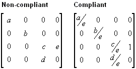
Recommended: Fortect
It is worth reading these fixing methods if you see Directx 10 Projection Matrix error code on your PC.
- 4 minutes read.
They believe that projection transformation should definitely be viewed as observing the internals of a camera; it’s like choosing a lens for each camera. This is the most difficult of the three types of transformation. This discussion of projection consists of transformations, divided into the following topics.
Recommended: Fortect
Are you tired of your computer running slowly? Is it riddled with viruses and malware? Fear not, my friend, for Fortect is here to save the day! This powerful tool is designed to diagnose and repair all manner of Windows issues, while also boosting performance, optimizing memory, and keeping your PC running like new. So don't wait any longer - download Fortect today!

The matrix of the projector screen is usually a perspective projection measurement. Transforming a projection means looking into a cone truncated by a cuboid shape. Since the near end, which is most often associated with viewing a frustum, is smaller, so it can be farther away, this leads to an expansion of objects that may be near the camera; He literally applies perspective to the scene.
In the view cone , the large distance between the camera and the origin of the view transformation space is actually arbitrarily defined as D, so the entire projection matrix looks like the following figure.
In raster view, the camera translatesto the origin by moving it -D in the z direction. The translation matrix undoubtedly corresponds to the following figure.
Multiplying the translation matrix by the projection matrix (T * P) can create a composite projection matrix, as shown in the following figure: Perspective
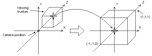
The transform moves the render stub into the current coordinate space. Note that the entire trunk becomes rectangular and our own origins move from the cabinet in the upper right corner of the scene to the store, as shown in the important diagram.
In perspective transform, the limits of the x and y directions are -two and 1. The limits of all z directions are 0 for prime and level 1 for the return plane.
This matrix transforms and scales the bits and parts entirely based on the specified distance between the near clipping plane and the camera, but does not take into account this field of view (fov) and the overall z-values it generates for an obstacle in the distance can be roughly the same, which makes it difficult to compare in detail. The following matrix addresses these issues and customizesIt sets the vertices according to the aspect ratio of the window, making it a good choice for perspective projection.

In this matrix, Z ‘is the Z value of the trimmed near plane. The variables w, r and q have been updated as follows. Note that fov w and fovâ‚– represent the horizontal and vertical view objects in the window in radians.
Using field of view angles to determine the current x and y scale factors may not be as convenient for your product when using the horizontal and vertical shapes and sizes of these windows (in camera). As you continue to calculate, the following two equations use all window sizes and are equivalent to your current previous equations.
In these formulas, Zâ ‚™ specific represents the position of the near cutting plane, and the variables V w and Vâ‚ • represent the width and top of the window in SLR space.
For a C ++ application, these two dimensions directly correspond to the width-plus-height elements of the D3DVIEWPORT9 structure.
Whichever algorithm you choose, be sure to set Z ‘as high as possible, sinceAt the same time, Z values that are very close to the target do not differ much. Makes some depth comparisons with a 16-bit Z-buffer relatively tricky.
As with world and discovery transforms, call IDirect3DDevice9 :: SetTransform to set the projection transform.
Setting The Projection Matrix
The next test function, ProjectionMatrix, defines the clipping planes for the front and back, as well as the predominantly horizontal and vertical field of the image corners. Fields of view should be seriously less than pi radians.
D3DXMATRIXProjectionMatrix (constants are near_plane position, // Distance to when clipping // Airplane const float far_plane, // distance to far clipping // Airplane const float fov_horiz, // Horizontal Test Field // Pose in radians const float fov_vert) // Vertical Field Of View // angle in radians drift h, w, Q; w = (float) 1 / tan (fov_horiz * 0.5); // 1 / tan (x) == bed (x) h = (float) 1 / tan (fov_vert * 0.5); // 1 / tan (x) == bed (x) Q = far_ plane / (far_ plane, includingi near_ plane); D3DXMATRIX ret; ZeroMemory (& ret, sizeof (ret)); ret (0, 0) = w; ret (1, 1) matches h; ret (2.2) = Q; ret (3, 2) equals -Q * near_plane; ret (2, 3) = 1; ret clause; // end of projection matrix The D3DX Utility Library provides the following functions to help you set up the projection matrix.
- D3DXMatrixPerspectiveLH
- D3DXMatrixPerspectiveRH
- D3DXMatrixPerspectiveFovLH
- D3DXMatrixPerspectiveFovRH
- D3DXMatrixPerspectiveOffCenterLH
- D3DXMatrixPerspectiveOffCenterRH
W-compatible Projection Matrix
Direct3D can use the new W-component of the transformed worldview vertex as well as projection matrices to implement depth-based information in depth buffering or fog effects. Such calculations require the individual’s projection matrix w to be normalized to be equivalent to the z-space. In the rare cases where the matrix projection contains a large coefficient (3.4), which is not easy, you will need to scale all types of coefficients with inverse coefficients (3.4) in order to create a tactical matrix. If you do not provide an update Matrix, fog effects and deepcast will not be applied correctly.
The following example shows a mismatched projection matrix in which the same matrix is scaled to account for relative eye fog.
In my previous matrices, all variables were assumed to be non-zero. For more information on eye mist, see Eye-Relative and. Z-axis depth . For information on w-based depth buffering, see Depth Buffer (Direct3D 9) .
Direct3D uses the current projection matrix for w-based depth measurements. Hence, applications must capture the conformal projection matrix to guarantee the desired w-based functionality, even if they are not using Direct3D in terms of transformations.
Download this software and fix your PC in minutes.
Directx 10 Projectiematrix
Macierz Projekcyjna Directx 10
Directx 10 프로젝션 매트릭스
Matrice Di Proiezione Directx 10
Matriz De Projecao Directx 10
Matrice De Projection Directx 10
Matrica Proecirovaniya Directx 10
Directx 10 Projektionsmatris
Directx 10 Projektionsmatrix
Matriz De Proyeccion Directx 10